Use Case
The aim of the this project is to provide an effective end-to-end solution of the following problem – how to generate universal automated link between human design thinking and cyber-physical systems (CPS) run-time environment. The resulting model-based framework can be divided into three parts:
- Design modelling environment
- ICT framework
- Operation environment
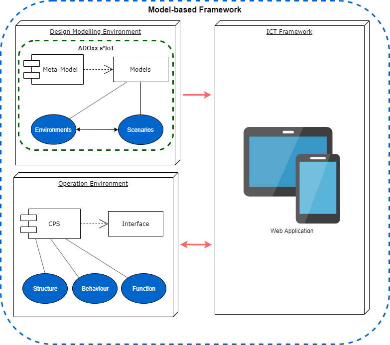
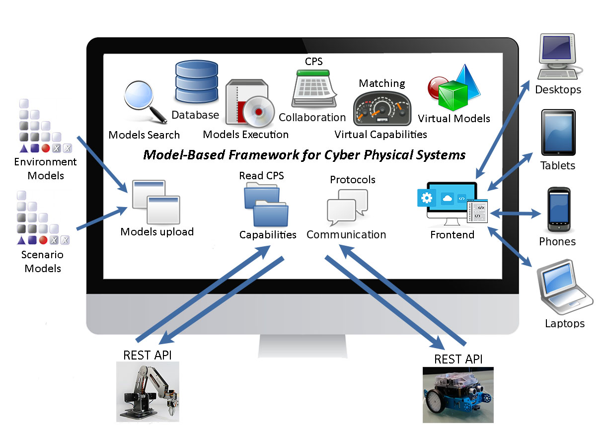
The ICT framework provides a connection between the design modelling environment and the operation environment. It consists of many different modules, with different roles:
- Models upload – the both types of models Environments and Scenarios are imported into the ICT framework.
- Read CPS Capabilities – allows the user to acquire all CPS capabilities and their properties and saves them into the database (API Endpoints and parameters).
- Protocols, Communication – the role of this module is to maintain the two way connection channel with the CPS (requests and responses) and to provide the output to the necessary modules.
- Frontend – responsive, reliable and fast, the Frontend is very important part of the ICT framework, giving to the user the possibility to control every process, to trace the execution, to make decisions during execution, to review the models and their properties, to select which pair of models should be executed together and so on.
- Models Search – for even greater user convenience, there is a models search bar in the navigation, which gives a short-cut, to search for every possible model, regardless of the current location of the user on the platform.
- Database – important structure in this thesis, allowing the users to save their models, CPS types, commands, matched endpoints and everything important related to the platform for further usage.
- Models Execution – this module serves to execute a pair of models, always one Environment and one Scenario, presenting the whole process on the Frontend and if necessary asking the user for input.
- CPS Collaboration – the collaboration between CPS is not a trivial task. In order to maintain it, usually there are some sensors and widgets involved. The collaboration means that one CPS can execute a specific action and react properly, depending on another CPS actions.
- Matching Virtual Capabilities – the Scenario model element commands are matched with the actual extracted CPS capabilities, during the Scenario model upload process. The user can select the corresponding CPS Endpoint and the necessary parameters to particular triples.
- Virtual Models – after the models are imported into the platform and inserted into the database with their properties, the ICT framework generates a virtual copy of them for more convenience. The user is able to see all the contained model elements and their features.
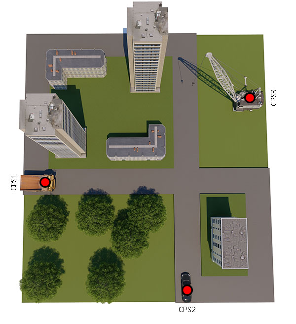
The design modelling environment consists of meta-model and two types of “smart” models, invented in relation to design thinking and satisfying the CPS run-time environment needs. They are all part of the s*IoT conceptual modelling framework.The two types of “smart” models are respectively: Environments and Scenarios. The Environments describe the surrounding area, the conditions, how many and what kind of robots are used and their starting points. Every robot has his own properties like host address and CPS type, which are stored inside the “CPS Starting Point” element. As a prototype two types of robots will be used: Makeblock mBot and RoboticArm.
If a new CPS type (new type of robot) needs to be added to the radio box, the process goes through “ADOxx Development Toolkit”, where under “Class Hierarchy” -> “_D-construct_” -> “_Conceptual_” -> “_Annotation_” -> “CPS Starting Point” the attribute “CPS Type” should be extended.

The Scenarios represent a process, based on a flowcharting technique similar to BPMN. The process describes the operations, which the robots are going to perform, divided into tasks.
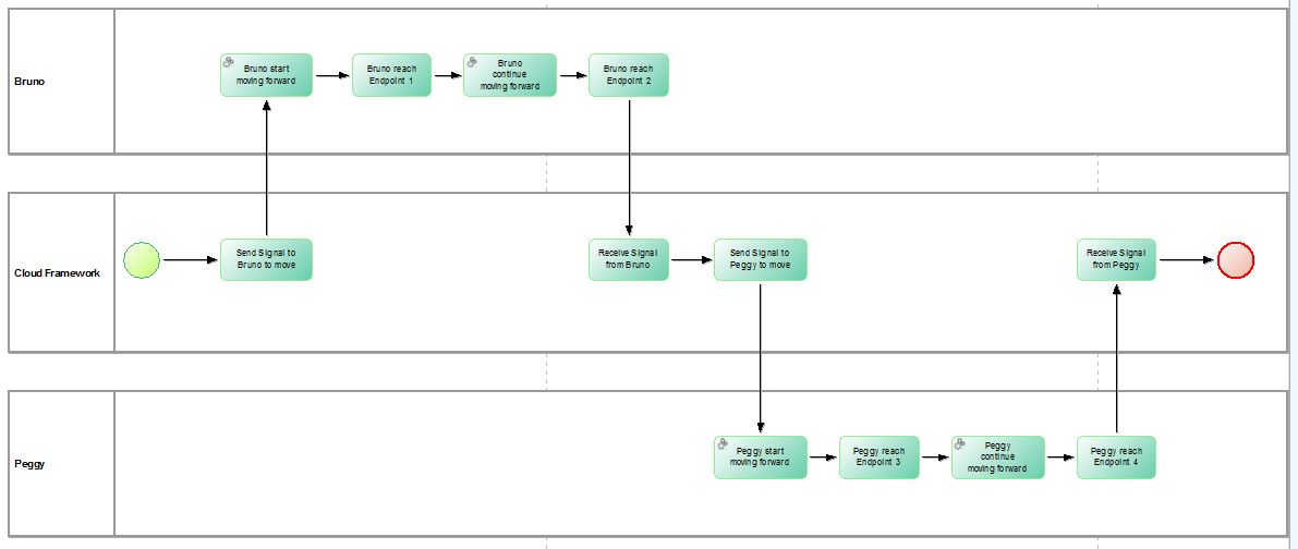
Every Scenario model must include only one “CPS Start Event” and only one “CPS End Event”, defining where the process starts and ends. The model can be infinitely complicated, including exclusive and non-exclusive gateways (parallels and decisions).
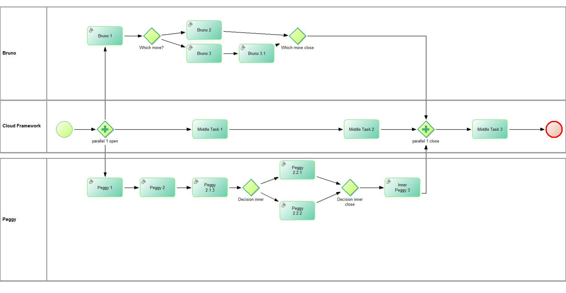
Every time, when there is a need of parallel or decision, open and close element should be placed inside the model, describing where the parallel/decision process starts and ends.
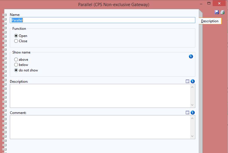
Every exclusive/non-exclusive gateway has sub-property “Function” (inside category “Description”). It should be set to “Open” or “Close”, depending if the parallel/decision process starts after this element or ends here.
Every pool inside the Scenario model represents a CPS or the framework itself. For this purpose the user designing the model should connect the desired pools with starting points from the Environment model through the category “Positioning”.

The “+” or “Add” button on the top right corner is used to add or edit a connection. A pool can be connected to multiple starting points from different Environment models (representing for example different types of devices), the only important rule is: Every pool can be connected to exactly one “CPS Starting Point” from a single Environment model. If the user adds more than one connection for example to two starting points from the same Environment model, error will occur during the import (in the framework).
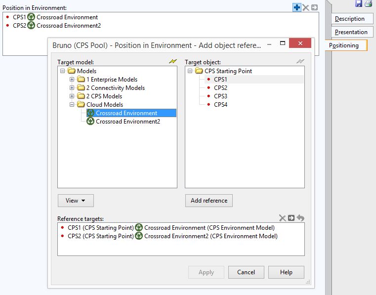
All tasks inside a pool will be performed during execution of the model on the connected starting point (more precisely on the connected robot/CPS, which this starting point represents).

The CPS Tasks have three main properties – Description, Task type and Execution.
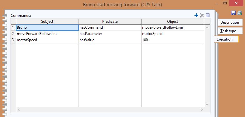
The “Execution” property represents the command and the parameters, which are going to be executed from the robot on this step. The commands, parameters and their values are described in the form of triples.

The “Task type” property represents what this particular task will be used for. If the task type is “Not specified”, usually this task has only “design” thinking role and is used in order to show what happens inside the framework after or before specific action. If the task type is “Not specified”, usually the “Execution” property doesn’t contain any commands.
Task of type “Function” means that the robot will execute some action and usually this task contains command and parameters inside the “Execution” property.
Task of type “Communication” is used only inside Non-exclusive Gateway/Parallel element.
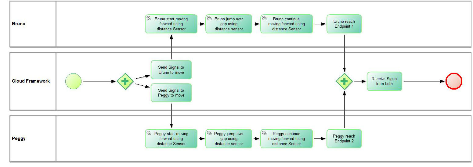
Task type “Communication” can be used for now only with CPS type mBot, which means that the pool has to be connected with starting point, representing robot of type mBot. Task Type “Communication” indicates that before executing particular command (described in task “Execution” property), the mBot will use his “distance” sensor to calculate the available distance in front of him. If the received distance number is less than certain threshold (meaning that there is an object in front of the mBot on a close distance), the mBot will wait for the other parallel task being executed to finish and will start with the current task again. This way a possible collision can be avoided.
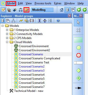
In order to upload the models into the framework and execute them, they first need to be exported from the ADOxx Modelling Tookit.
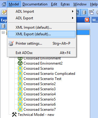
A model can be exported through the “Import/Export” button in the main menu. After “Import/Export” is selected, under “Model” dropdown in main menu, there is an item “XML Export Default…”
By clicking on this item, a pop-up will appear. First the desired model for export should be selected from the sub-window “Models”. Under the “File” sub-window, a file should be created or replaced in which the XML will be saved.
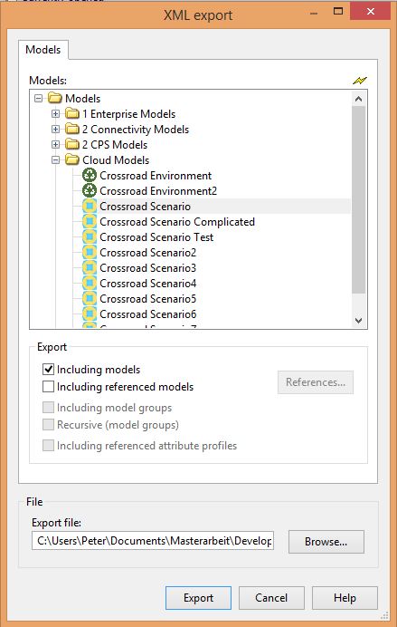
Clicking the “Export” button will finish the operation and now the file will be available for upload into the framework.

There is a button “Model Upload” – for both types of models. The system recognizes automatically, what type of model is uploaded. In order to upload a particular Scenario model, first all connected Environment models should be uploaded. If the user tries to upload a Scenario model, before the corresponding Environment models, an error will occur.
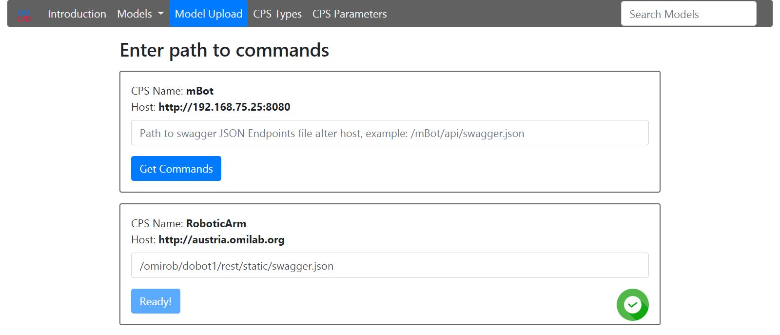
After an Environment model is uploaded, if his CPS Starting Points contain new CPS Types, still not existing in the platform, an input field will appear for each one of them. The corresponding path to the swagger JSON file (describing the Endpoints structure of the CPS so that machines can read it) should be entered. After clicking the “Get Commands” button, a status will appear. If the commands are read successfully, the button will be disabled and success icon will appear on the right side.

If the entered path is wrong or if there is any type of connection problem with the device, the button will be available again and a fail icon will appear on the right side.
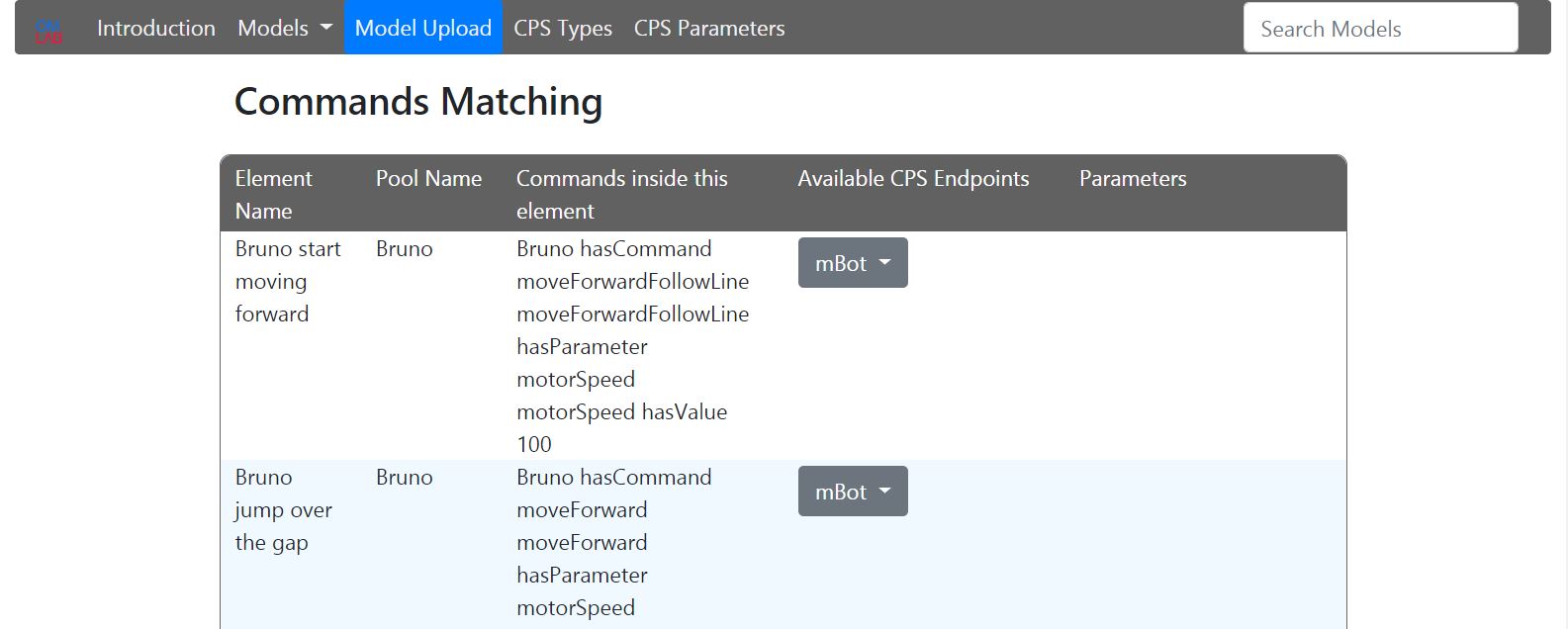
After a Scenario Model is uploaded a select will appear for every task with command, for each unique connected “CPS Type”. A corresponding CPS Endpoints should be selected. If the Endpoint also contains parameters, they will appear.
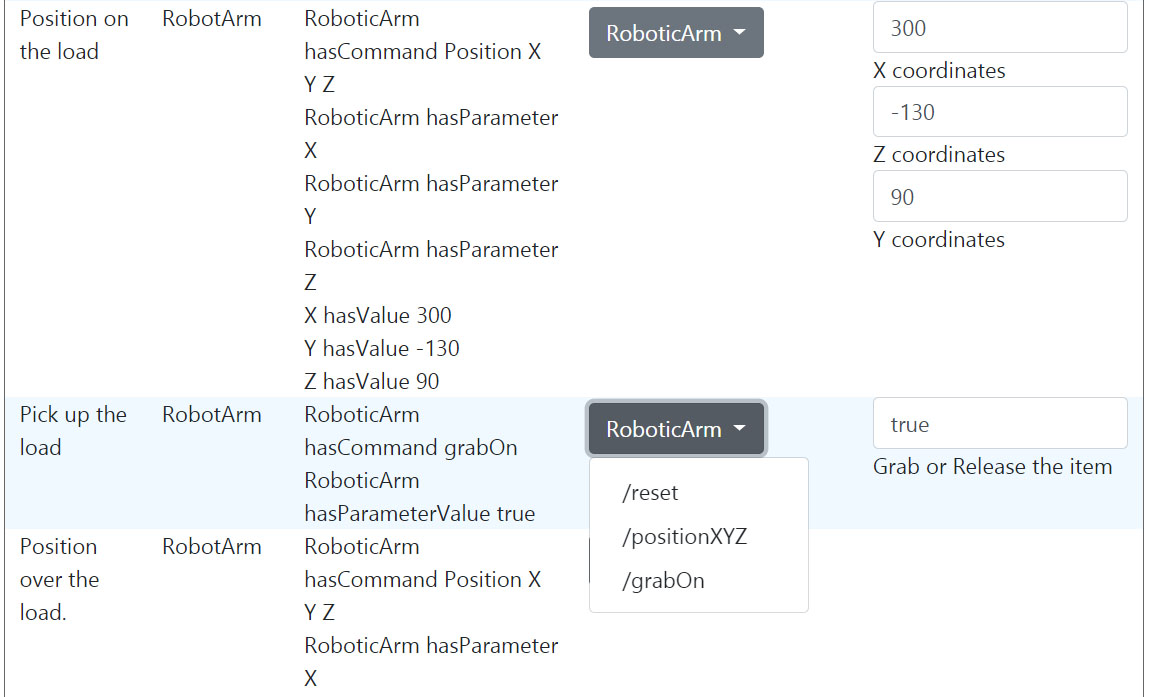
After all Endpoints are selected and the corresponding parameters are entered, the save button should be clicked. Now the models are ready for execution. The connection between the models is many to many, but during execution always one Environment Model is executed with one Scenario Model.
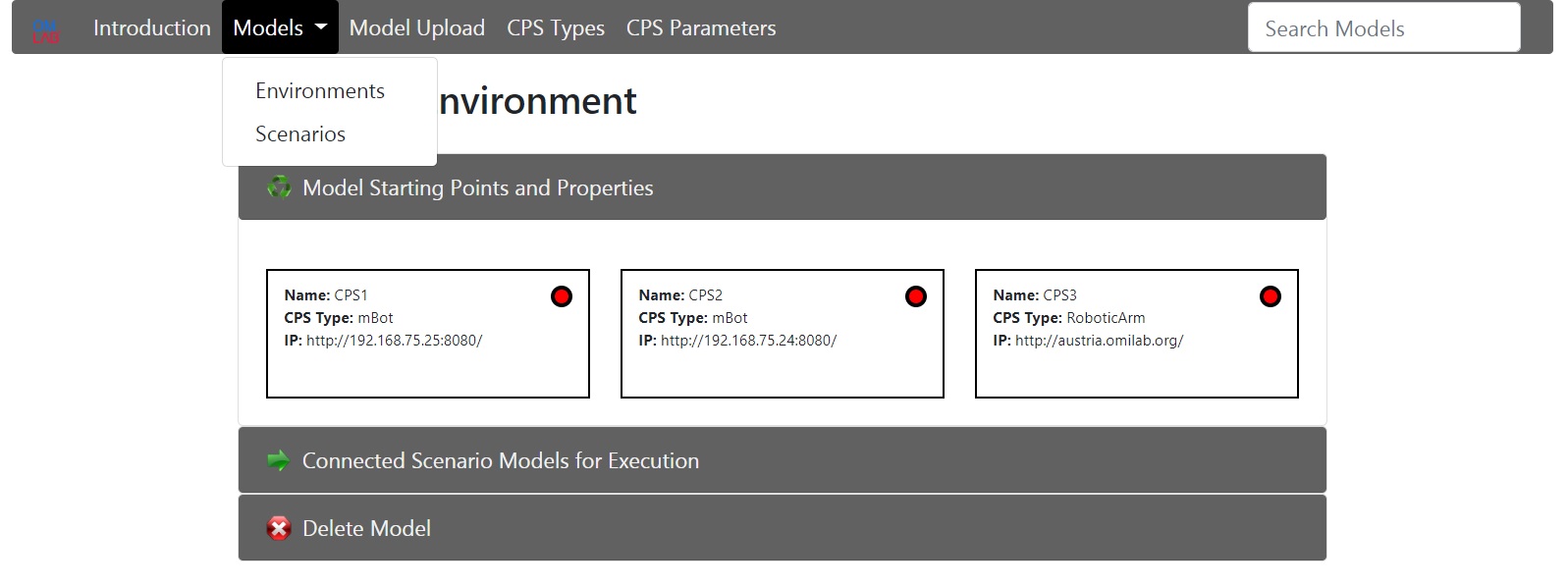
A model for execution can be selected through the dropdown menu “Models”. In every model, there is a collapsible item “Connected Models for Execution”. If a model is selected, the execution process starts. There is also collapsible item “Delete Model”. The models must be deleted in the same order, as uploaded. This means, that in order to delete specific Environment model, first all connected Scenario models should be deleted.

There is a extra menu item “CPS Types”. From here the user is able to delete existing CPS Types, for example when a particular CPS has updated swagger JSON file and the user needs to load all Endpoints again or also in cases where during the Environment model upload, the commands haven’t been read correctly. In order to delete particular CPS Type, first all Environment models containing this CPS Type should be deleted.

The last menu item is “CPS Parameters”. All existing Endpoint parameters have a description coming from the swagger JSON file. This description can be edited for more comfort. Usually the description of a parameter describes, what this parameter is used for. In our case, in the framework it would be more meaningful, that the parameter describes, which value or what range of values should be given.
On the top right corner of the platform, there is a search box for models.
Experiment
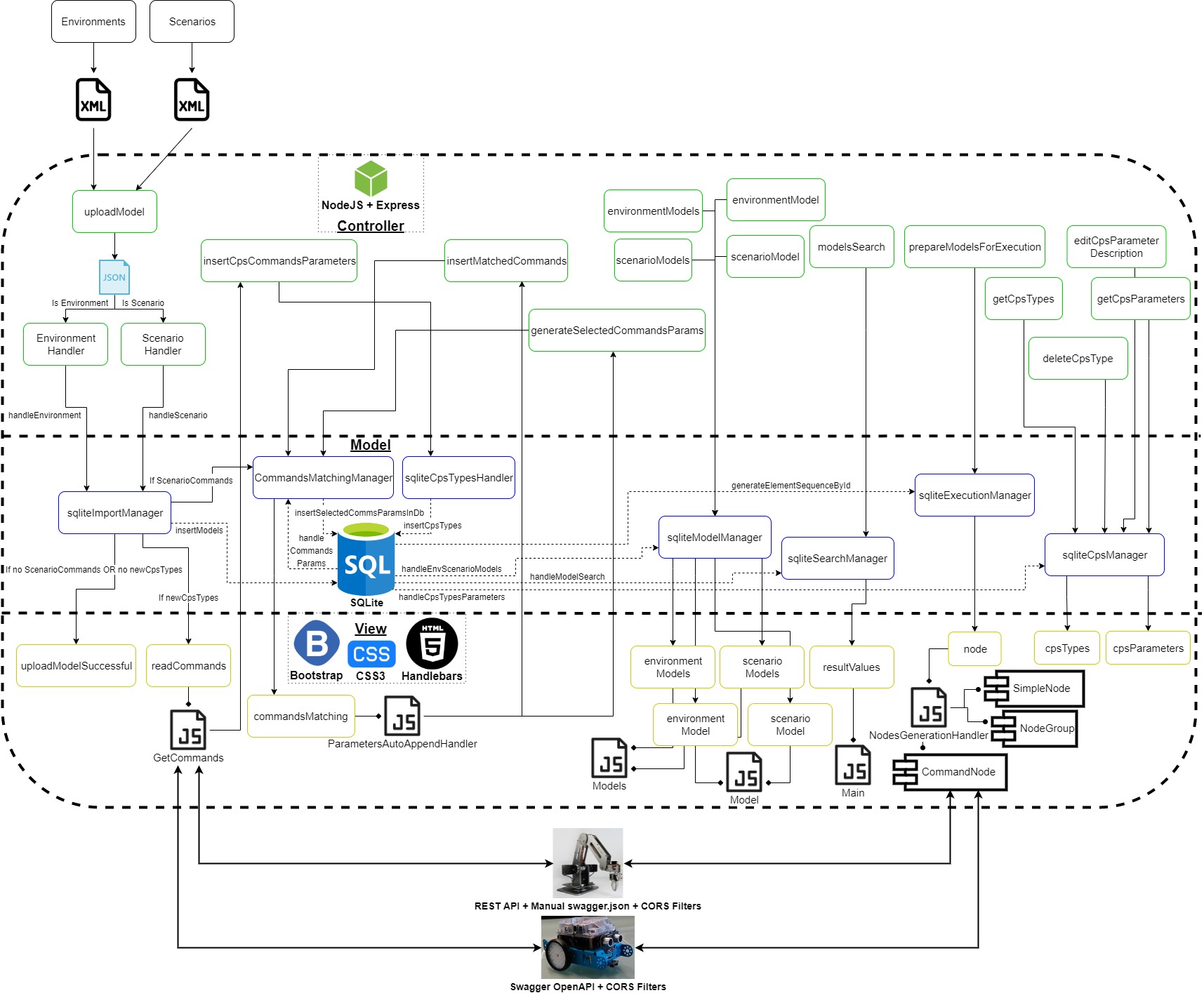
This part explains how the ICT framework is implemented and what parts it consist of. The system can be split logically into several general modules. The ICT framework is built according to the MVC software design pattern. The figure below gives an overview of the whole architecture and the relationships between the different modules.
1. Database
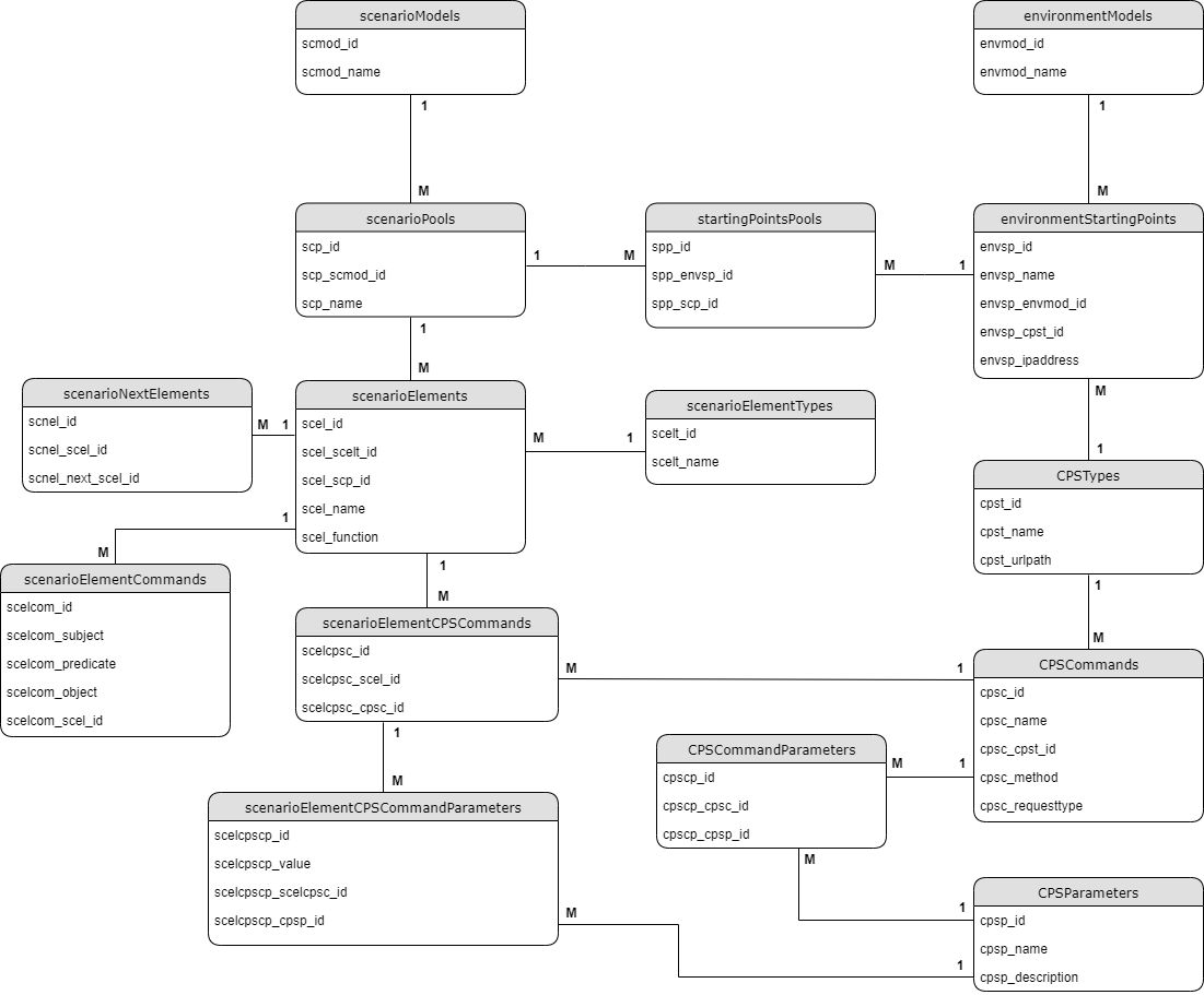
The database is implemented with SQLite, which is an small, fast, open source, self-contained relational database engine, that supports all SQL features. It doesn’t need any configuration, installation or server process. It is embedded directly inside an application. The whole database is contained into one single file. The only thing necessary to access the database file from an application is external module, which fulfills the connection. SQLite supports one particular module called “sqlite3” for two-way connection with the database file. The module provides control over queries, debugging support, error forwarding, serialized and parallel query execution flow, query placeholders (against sql-injections).
The database structure represents the model-based framework needs. There is a table for every type of model – Environment and Scenario. As follows the Scenario models contain pools, the pools contain elements (Start event, End event, Tasks, Exclusive gateways, Non-exclusive gateways) and the elements contain commands and parameters (in the form of triples – subject, predicate, object). The table “scenarioNextElements” describes the element sequence inside the Scenario model. The table “scenarioElementTypes” contains all of the element types mentioned above. This table is the only static table from the whole database, which can be edited only from administrator. A new record should be inserted in this table, in case of a new type of element is invented and added to the Scenario models. On the other side the Environment models contain starting points. The connecting point between the both types of models is the middle table “startingPointsPools”. As the user connects pools from scenario models with starting points from Environment models, a table between these two elements is sufficient. Also the starting points may contain CPS Type, which CPS Type has particular “CPSCommands”. There is a middle table between the “CPSCommands” and “CPSParameters”, as in many cases there is one parameter belonging to more than one command (Endpoint), and also the commands (Endpoints) can have many parameters. The connecting point between the scenario elements and the CPS Commands is the table “scenarioElementCPSCommands” and “scenarioElementCPSCommandParameters”. It will be explained later how this table is filled up.
2. Frontend
The frontend part of the model-based framework is implemented in JavaScript, Express Handlebars, CSS3 and Bootstrap. Express is flexible NodeJS web application framework, which provides many important features. It is very well suited for both web and mobile applications. Express can be described as server-side rendering tool. It uses middlewares, routing and allows dynamic rendering of HTML pages. The important variables are send directly from the backend side of the framework as parameters and visualised in the HTML templates. Also to be able to build specific semantic templates, next to Express a view engine called Handlebars is used.

The picture above is an example for Express routing, or more precisely how the framework endpoints respond to client requests. When a particular endpoint (URI) is requested, the corresponding function is executed. The Handlebars view templates can be described as HTML files with extra functionality inside them. In order to provide more properties to the HTML elements and to give the user visual experience, CSS3 and Bootstrap are used. CSS defines how the HTML elements are arranged on the screen and describes the style of the web page like colors, fonts, shapes. The other big issue is, that the user should be able to use different devices with different screen resolutions (from smartphones to PCs). With the help of CSS3 and Bootstrap website can be made in a way, that looks similar on all kind of devices and platforms. This process is called responsive web design. Responsive means that every HTML element has corresponding size and position depending on the target device and resolution. Text size and arrangement of elements also change. Bootstrap is a frontend framework created by Twitter for developing of responsive web design, which combines HTML, CSS and JavaScript. It is open-source and every feature or template can be extended by the developer, depending on the specific needs. In this master thesis bootstrap grid system is often used.
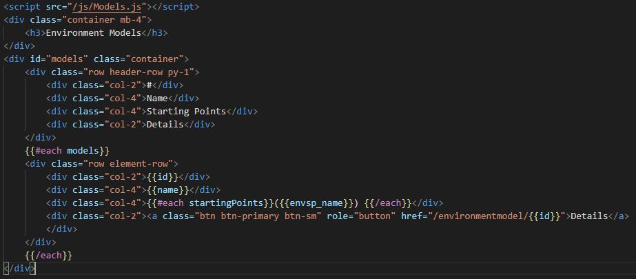
The grid is table-like system, which is separated into 12 columns. The developer can aggregate as many columns as needed into a single column. This allows the columns to have different sizes. They and the objects inside them, resize proportionately to the screen size.
3. Upload and Commands-Endpoints matching
The upload module is separated into three sub-modules. The first one is XML-Parser who deals with the reading of the important branches from the model XML tree. The second one inserts the extracted data into the database. The third one takes care for the swagger JSON file, which should be read from the target CPS. In order to convert the received XML models from ADOxx, an external library called “xml-js” is used. The library transforms XML into JSON.
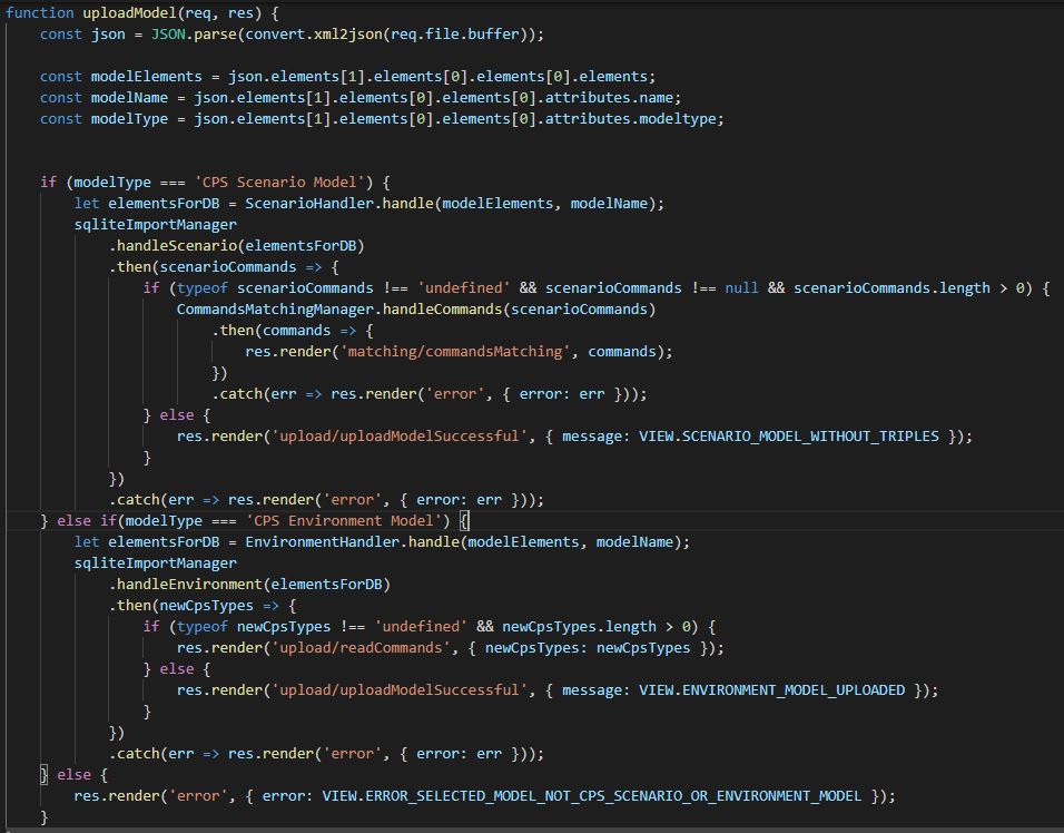
After an Environment model is converted to JSON, the “EnvironmentHandler” class generates a structure with model attributes and pass them to “sqliteImportManager”, which inserts the data into the database. Because of the asynchronous nature of JavaScript, each query is executed sequentially. For this purpose promises are used.

The promises execute each function, wait for it to finish and to return some output value. Then they continue with the next function, giving as input the received value. One promise has three possible states: resolve, reject or pending. Resolve means that the function is executed successfully and the value is received. Reject means that some error occurred during execution and Pending means that the function is still executing.
As the functions from the picture above are mostly self-explaining, it is important to note, that on the first step “checkEnvrionmentModelByName” checks if model with same name already exists in the database. If it exists error occurs on the frontend. The function “checkCpsTypesExist” does the same, but for new CPS types.
After the model and his starting points are inserted, if there are any new CPS types missing from the platform, the user is redirected. When the user enters some path to swagger JSON file, a request is performed. JavaScript contains default method for requests called “XMLHttpRequest”. Again the request is closed inside promise, which resolves only if the target file is successfully read.
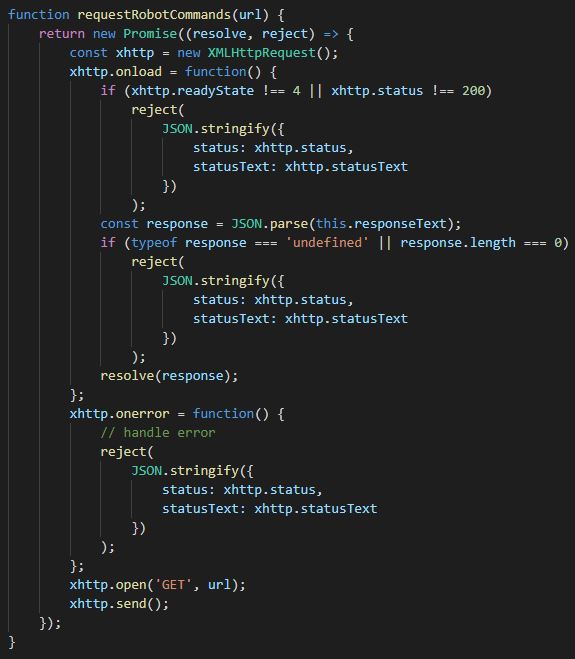
After the file is read, the Endpoints are extracted and inserted into the database. Correspondingly the frontend side is also updated and the user receives confirmation if the operation is finished successfully. The both modules “Upload” and “Commands-Endpoints matching” are closely related. They are both part of the Scenario model upload process.
The main difference from the Environment model upload is, that the Scenario model contains much more different elements, which also have to be inserted sequentially in order to build the right connections between elements.

When a Scenario model is inserted into the database, also the middle table between scenario pools and environment starting points is filled up. If the scenario elements (mostly tasks) contain commands, in the form of triples, the user is redirected. Here the module “Commands-Endpoints matching” is involved. The user has to select, which element with triples correspond to which CPS Endpoints. When a CPS Endpoint is selected, a query is executed and the corresponding parameters are appended.
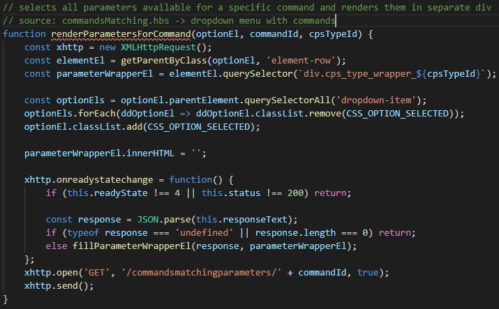
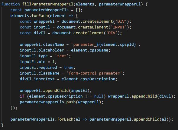
After all the information is entered and the “Save” button is clicked, the important data is extracted from the different HTML elements and then is inserted into the database.
4. Models
The models module is separated into four sub-modules: Environment models, Scenario models, Single Environment model and Single Scenario model. The first two sub-modules are displayed in a table form. The corresponding models and their properties are selected from the database and rendered. Again the bootstrap grid system is used.

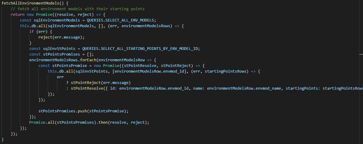
From the resulting table the user is able to open a single model (either Environment or Scenario). Both single Environment and single Scenario models are separated into three collapsible sections. For this purpose Bootstrap Collapse (Accordion) is used. By the Environment model in the first section are described all the starting points and their properties. They are also sorted in alphabetical order by name. By the Scenario model, the first section contains all elements, including the pools, in which they belong. The elements are sorted with a recursive function, which takes the element in the exact sequence from the model. If there are any Non-exclusive Gateways (parallels), the function takes the elements from each edge in sequential order.

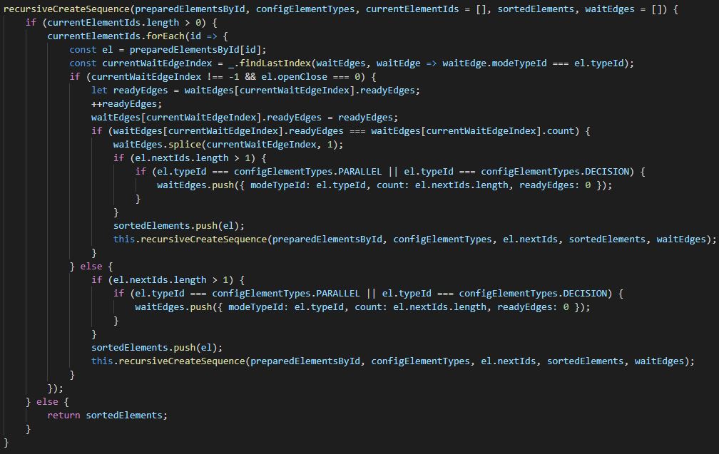
The second section by both single Environment and Scenario model contains all the the possible pair-models, which this model can be executed with. In order for the execution process to work properly, always two models are needed – one Environment and one Scenario. As described earlier, during modelling the user can connect a single pool to many different starting points, from different Environment Models. That makes the connection between models – many to many. So in this section the user is able to see which exactly are the connected pair-models to the selected model. The last section “Delete Model” is implemented with Bootstrap Modal. It opens a modal window for confirmation of the deletion process.
5. Execution
The final step in the framework is the execution of the models. Here all the individual pieces described until now are connected. As mentioned earlier for a proper execution, two models each from each type are needed – Environment and Scenario. They both need to be connected. First as both model ids come as GET parameters, they are parsed as integers. Then the element sequence is generated. All elements from the selected Scenario model are fetched from table “scenarioNextElements”. Next their CPS corresponding properties are added from the selected Environment model (respective the CPS Type id, CPS Type Name, IP address, URL path). On the next step the CPS Commands are added to the corresponding elements (CPS Endpoint – the Endpoint was selected earlier during Scenario model import from user, method – POST, GET or PUT, request type – JSON, Boolean and so on). Then the corresponding CPS Endpoint parameters are also added to the elements. Finally the elements are restructured, where every element is identified by id and the following elements are saved into arrays. If the request method is GET for some element, the parameters are replaced with their values in the Endpoint with regular expression. When the new element structure is ready, it is send to the frontend.
On the frontend side first it is checked if there exists some kind of CPS, which requires Authentication Token. If such token is needed, the user is asked to enter it. Then all the elements are send to a recursive function, which generates the Nodes sequence.
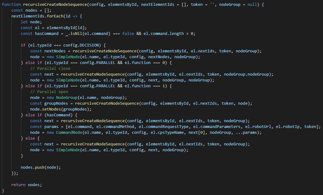
The “CommandNode” represents class, which contains command (Endpoint) with/without parameters. The “NodeGroup” represents class, which is of type Non-Exclusive Gateway (Parallel). All other elements, including normal tasks, start event, end event, Exclusive Gateway (Decision), which don’t contain commands are processed as “SimpleNode”. The main role of “NodeGroup” is to add all elements inside of this parallel into this particular “NodeGroup”, in order for the process to know where the parallel starts and who is responsible for the execution of the elements inside of it and also where does the parallel ends.
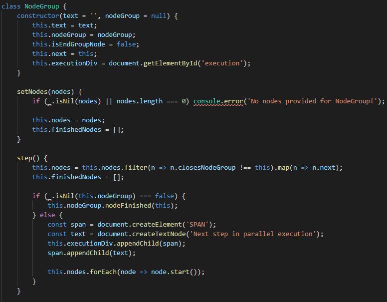
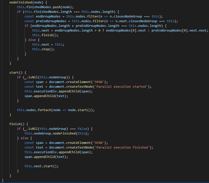
The elements inside a “NodeGroup” are executed step-wise. This means, if there are for example three edges after parallel start, on each step one element will be executed from each edge, until the particular edge is finished and the parallel end is reached. If for example one edge is finished and there are still remaining elements on the other two edges, they will continue executing step-wise, until the parallel end is also reached there. When all edges reach the end parallel element, the “NodeGroup” is finished and the responsibility for execution is given back to the next element in the sequence. If a new parallel is reached inside one of the edges during parallel execution, the same process start there, where the new “NodeGroup” has the responsibility to execute the elements inside of it step-wise.
The Exclusive Gateway (decision) is “SimpleNode” type of element, because after decision is taken, there is only one next element (only one child) and also the decision elements (just like Non-Exclusive Gateways – parallels) are not allowed to contain any commands.
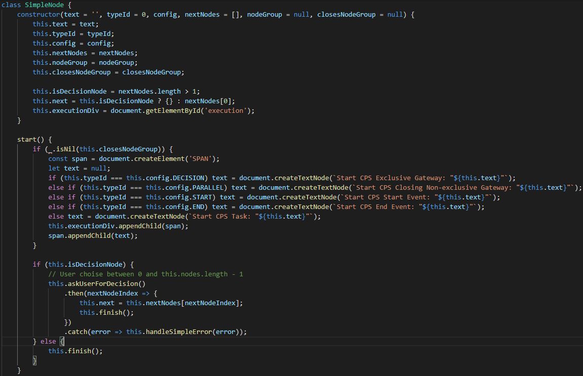
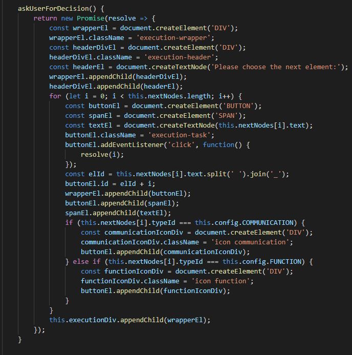
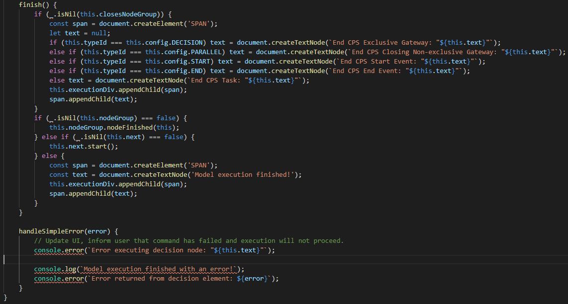
The “CommandNode” has three different types of HTTP requests, which it executes, depending on the request type of the command (Endpoint). For each single request type, according if it is GET, POST or PUT, also the parameters and the response are processed in different way. If the “CPS Type” is of type mBot, the element is of type “Communication” and the execution is currently inside “NodeGroup” (parallel) a specific request is made. First an HTTP request is performed to the distanceSensor of the CPS, the response is compared to a particular threshold, if the value is below the threshold, all other parallel elements in this step are executed and then a new HTTP request is performed again to the distanceSensor. If the value is above the threshold, the command (Endpoint) is now performed and execution of the model continues.
6. CPS
The CPS module contains two sub-modules: “CPS Types” and “CPS Parameters”. Both are represented with the help of the Bootstrap grid system. The idea of the “CPS Types” is to give the user possibility to delete CPS types through the interface, for example when the swagger JSON file has changed and the user wants to load again all available Endpoints and their parameters. When a CPS type is deleted, all belonging commands (Endpoints), parameters and records from their relationship table are deleted. The role of the “CPS Parameters” is to give the user the possibility to change the automatically read parameter descriptions from the swagger JSON file for more convenience.
7. Config
The Config module is just a simple fetch query to the table “scenarioElementTypes”, which as explained earlier is the only static table in the database. It selects all element types and give them back, where they are needed as JSON object. This object is used on many different places for comparing and more visibility.
